
A unique feature of the DSO is that while its name may imply "Digital Storage Oscilloscope" it is in fact a set of integrated "virtual instruments" (VI) that implement far more than just one scope.
DSO implements several types of digital instruments; a digital storage and sampling scope, a logic analyzer, a mixed signal scope, a spectrum analyzer and an integrated waveform generator.
The bar down the right side of the DSO is where the VI (aka operating mode), display and global control buttons are located.
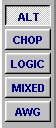
The set of buttons that appear depend on the type of BitScope that is connected and the selected VI. When connected to a BS50U for example the buttons available when the ALT VI is selected are:

POWER and SETUP are always present.
POWER: click to "switch on the DSO".
SETUP: click to open the setup dialog.
More information about setup and configuration is available here.
The selected virtual instrument configures the operation of DSO for different types of measurement. Usually you choose the most appropriate VI as the first step when performing a new measurement.
With BS120, BS220, BS300 and BS310 BitScopes the choices are ALT (alternating capture), CHOP (chopped capture) and MIXED (mixed signal capture). On BS440 CHOP and ALT are merged into one instrument (called SCOPE) and on BS50 an additional logic only VI (called LOGIC) is available.
BitScope models that include a waveform generator also include the AWG VI.
ALT is usually preferred for single or dual channel high bandwidth analog capture, CHOP for lower bandwidth phase aligned dual channel analog capture, LOGIC for high speed logic only capture, MIXED for analog + logic capture and AWG for waveform generation (and simultaneous waveform capture in the case of BS310 and BS440).
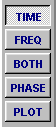
Below the VI selectors are the display selectors which vary according to the VI.
SCOPE, ALT, CHOP and AWG VIs have choices TIME, FREQ, BOTH, PHASE and PLOT.
The MIXED VI has choices MIXED, LOGIC and TIME.
The display selection is "modal". That is, if you change the selected VI, the display (and other settings like timebase) most recently selected for that VI will be restored.
Display selectors do not affect the way data is captured, only how it is presented on the display. They configure the X and Y axes, scaling and measurement units, graticule type, cursors and splits.
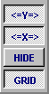
Below the display selectors are several global controls.
<=X=> and <=Y=> enable the on-screen cursors for precise time/frequency and voltage/level measurements.
HIDE flips the application between full control and hidden control view. When the controls are hidden the display expands to occupy the full application window.
GRID enables the measurement graticules.